Introduction
The “life of a packet” describes the journey a piece of data takes from a source device to a destination device across a network or networks. This process is governed by a layered model, most commonly the TCP/IP model (or the OSI model), which breaks down communication into manageable stages. Each layer adds its own header, like a series of envelopes, that guides the packet to its final destination.
Imagine sending a letter or package to a friend within your region or outside the country through a Parcel Delivery company. The letter contains your address (Source address) and the receiver (Destination address), these addresses can be used to represent the role of IP Address of a Packet in a Data Communication Network, which remains with the data throughout the journey. Sending the package from your residence to the company through local Courier requires your contact details and the Courier details to deliver the package to the company for tracking purposes, these details can be used to visualize the role of MAC address in Frame transmission within a local network, the company also uses different means to route the package, which requires details of the personnel moving the package and to where it’s to be delivered, this will keep changing from area to area, state to state, zone to zone, region to region or country to country as the case may be to reach the final destination.
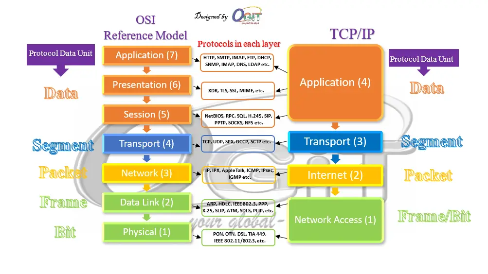
Let’s get to discussing the illustration above in details, using the TCP/IP model. The OSI model has seven layers, which is most preferred by Network Engineers/Administrators in troubleshooting network problems. However, the seven layers in OSI model are grouped into the four (4) layers of TCP/IP model. Layers in this blog refers to OSI reference model layers.
OSI reference model Vs TCP/IP model
Network models with protocols and PDUs in each layer
Layer 4: The Transport Layer (TCP/UDP)
The packet’s life begins at the Transport Layer,after the data have been formatted properly by the upper layer protocols through User Application Software and Operating System. Here, the data is segmented and a header is added.
WEB/DNS Server function Illustration
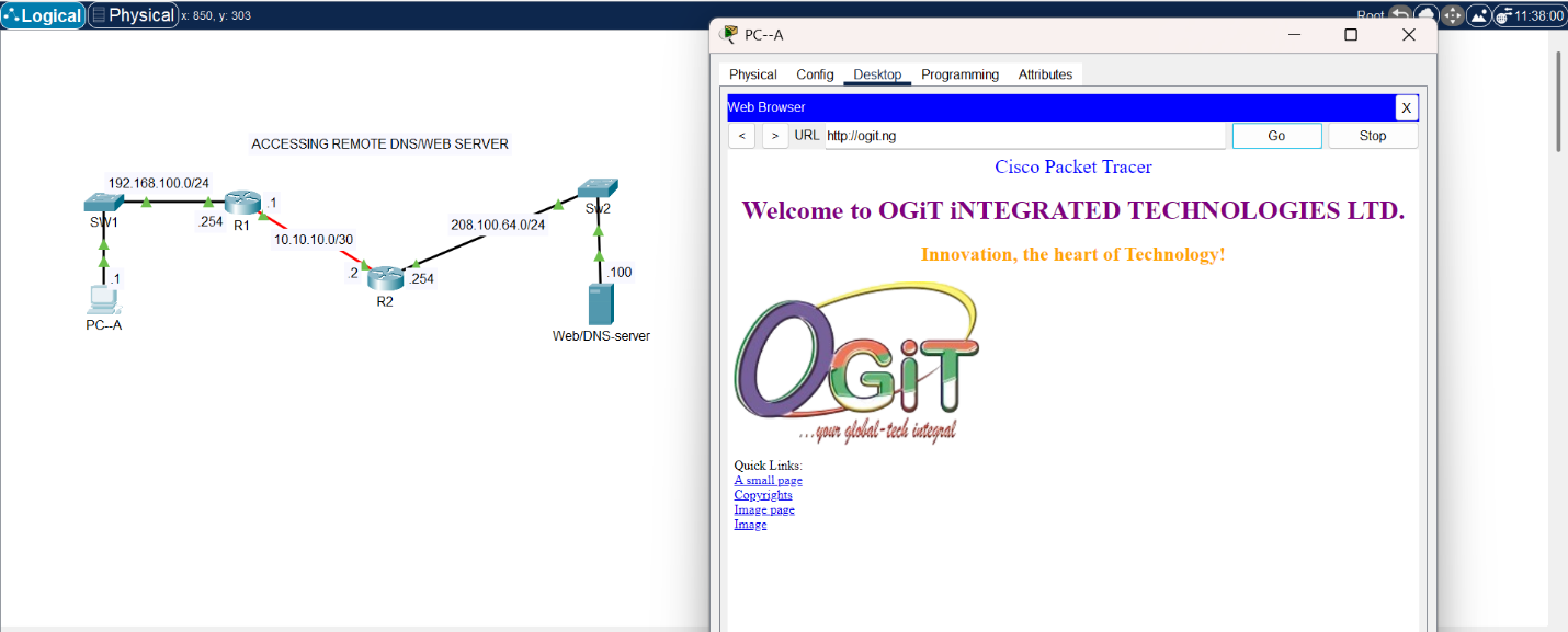
Accessing WEB/DNS Server
The topology in the image (Accessing WEB/DNS server services) uses both TCP/UDP headers in reaching out to the dummy OGiT website. The UDP is in action when the DNS server is reached to resolve ogit.ng to the IP address that is registered with the domain.
Data Segmentation in packet switched network
Data segmentation in packet switched network is the process of breaking down a large block of data into smaller, more manageable units called segments or packets. This process happens at the Transport Layer of the TCP/IP or OSI model to fit into the size acceptable on the link to the destination, such as Maximum Transmission Unit (MTU)in the fragmentation field of the IP header at the Network/Internet layer and Length field of the Ethernet header at the Data link layer. The smaller segments are then sent individually across the network and reassembled at the destination, each of these segments has headers that contains information to transmit the segments/packets to the destination and helps in reassembling. All the remaining headers encapsulation and decapsulation will be treated as we progress.
Data segmentation is a fundamental concept for several key reasons:
- Efficiency: Networks have limitations on the size of the data units they can transmit. By breaking down large files, a network can transmit smaller pieces more efficiently. It’s like shipping a large piece of furniture in boxes rather than as a single unwieldy item.
- Reliability: If a single large file were sent, and any part of it was lost or corrupted during transmission, the entire file would need to be resent. With segmentation, only the lost or corrupted segment needs to be retransmitted, which saves time and bandwidth. This is particularly important for protocols like TCP.
- Congestion Control: By sending data in small segments, network devices like routers and switches can manage traffic flow more effectively. If a network path becomes congested, smaller packets can be held in a queue or rerouted more easily than a large, monolithic block of data.
- Multiplexing: Segmentation allows a single device to handle multiple data streams simultaneously. Each segment from a different application (e.g., a web browser, a streaming service, and an email client) is given a unique port number, allowing the receiving device to distinguish and direct the data to the correct application.
The two main protocols at the Transport layer are TCP and UDP.
- UDP (User Datagram Protocol): This is a connectionless protocol. It is faster and has less overhead because it does not guarantee delivery. It simply sends the data without waiting for an acknowledgment. The UDP header is much simpler, containing only source and destination port numbers and a checksum. It’s used for real-time applications like video streaming and online gaming where speed is more important than perfect delivery.
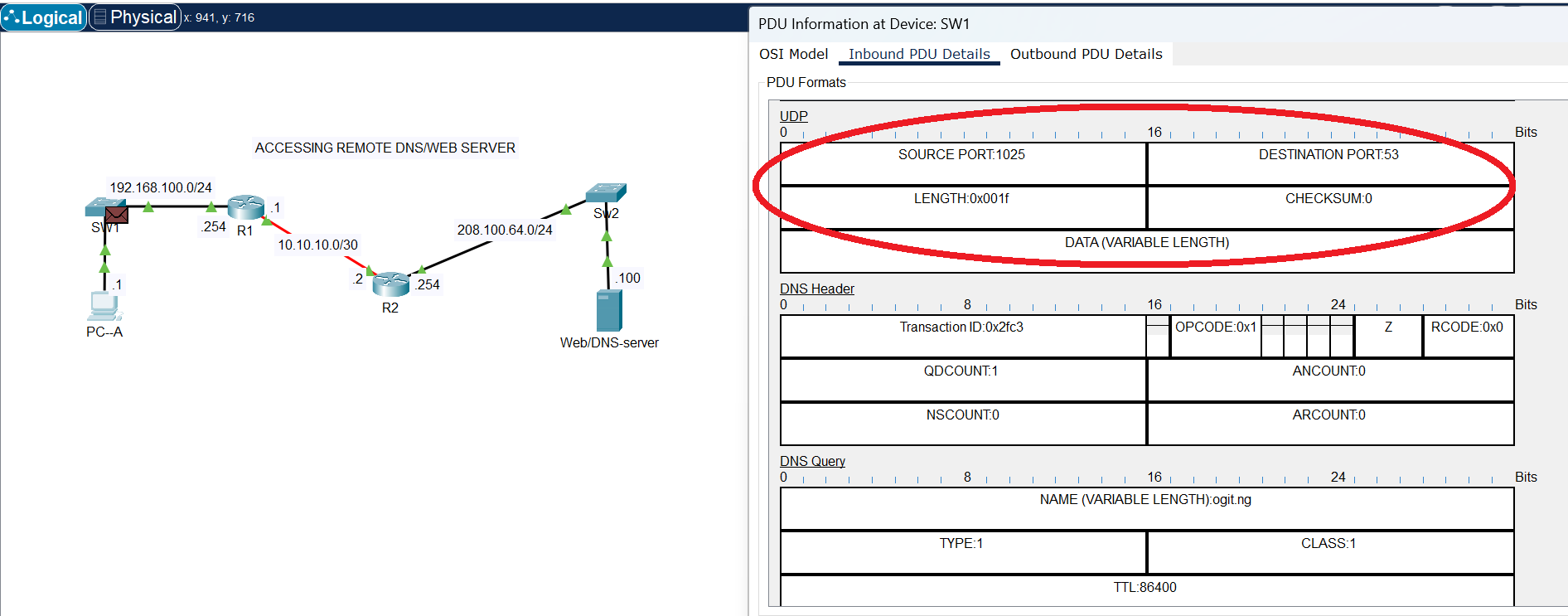
UDP Header
The image above shows the UDP header, that is being used by DNS service to reach the DNS server at destination port 53. DNS does not need acknowledgement; hence it operates on UDP at the transport layer.
- TCP (Transmission Control Protocol): This is a connection-oriented protocol. It ensures reliable delivery by numbering the segments and requiring an acknowledgment from the recipient. It adds a header containing source and destination port numbers, sequence numbers, and checksums. If a segment is lost, TCP will retransmit it. This is used for applications like web browsing (HTTP) and email (SMTP) where reliability is critical.
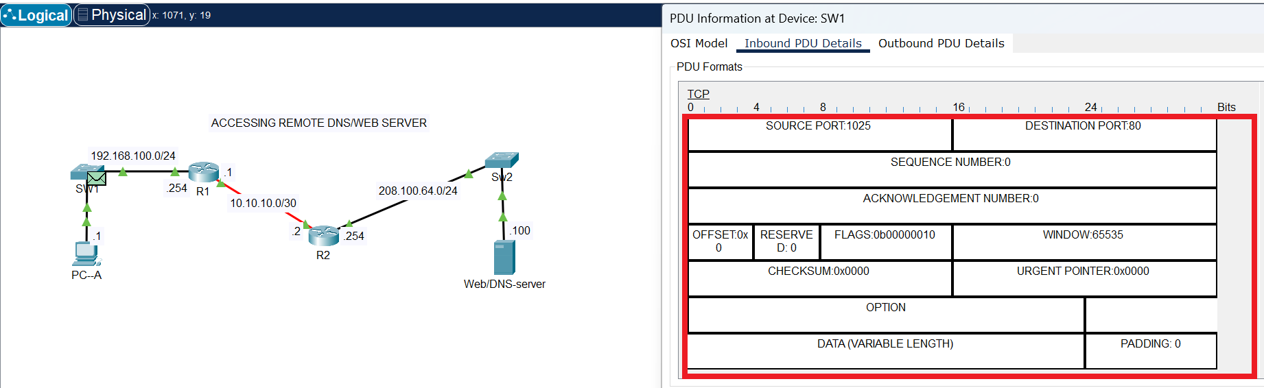
TCP Header
The request sent to the Web server is HTTP (non-secure), which listens on port 80, but requires acknowledgement to be sure the request is successfully delivered.The image above shows the fields in TCP header that are required to control the flow of segments for successful delivery.
Layer 3: The Internet Layer (IP)
After the transport layer, the segment is passed down to the Internet Layer. Here, the IP (Internet Protocol) header is added by a layer 3 device (router). This is one of the most crucial headers in a packet’s journey, as it contains the logical addresses needed to route the data across different networks.
IP Header
The header contains the source IP address and the destination IP address. The IP address is a logical address that uniquely identifies a device on a network. The IP header’s primary job is to get the packet from one network to the next until it reaches the final destination network. Routers use this IP address to forward the packet along the most efficient path. These logical Source and Destination addresses remain with the packet from original source to final destination, unlike the MAC address (physical Source and Destination addresses) that changes on each link as packets move on different local network towards the final destination.
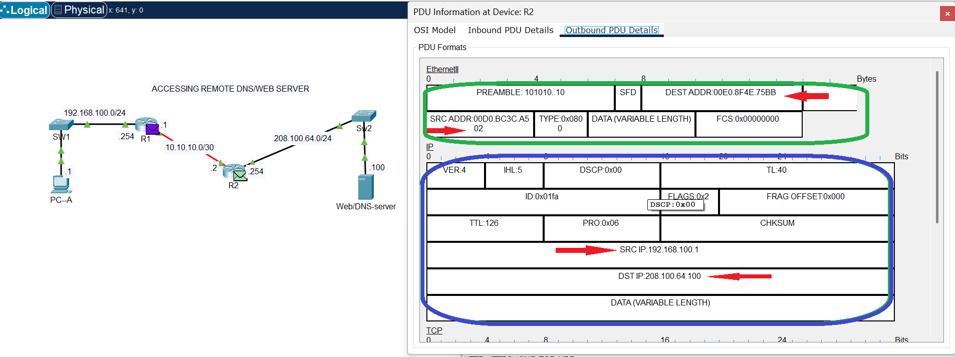
IPv4 Header
Take note of the Destination and Source IP addresses as displayed in the IPv4 header circled in blue ink, these remain the same throughout the journey of the packets from source to destination. However, at this point the Destination and Source MAC addresses have changed from the values at the source local network (Ethernet Header image), as indicated in green ink at the IPv4 Header image above.
Note: Source and Destination IP addresses are still the same with values at the source (see Ethernet Header Image below).
The IP (Internet Protocol) header is a crucial component of a data packet at the network layer. Its primary function is to provide the necessary information for a packet to be routed across different networks and reach its intended destination. Without the IP header, a packet would be unable to find its way through the vast network of the internet.
The IP header acts like an envelope for the data packet. It contains essential metadata that guides the packet’s journey from its source to its destination. The key functions include:
- Addressing and Routing: This is the most critical function. The header contains the source IP address (the sender’s address) and the destination IP address (the receiver’s address). Routers along the path read the destination IP address to determine the most efficient route to forward the packet.
- Packet Identification and Fragmentation: In IPv4, the header includes fields for Identification, Flags, and Fragment Offset. These fields are used when a packet is too large for a network’s maximum transmission unit (MTU) as mentioned in Data Segmentation in packet switched network section above. They allow the packet to be fragmented into smaller pieces and then reassembled correctly at the destination.
- Packet Lifespan Control: The Time to Live (TTL) field (or Hop Limit in IPv6) prevents a packet from circulating indefinitely in a network. Each time a packet passes through a router (a “hop”), the TTL value is decremented. If it reaches zero, the packet is discarded, preventing network congestion caused by lost or misrouted packets.
- Protocol Identification: The Protocol field (or Next Header in IPv6) identifies the protocol of the data being carried inside the packet (the payload). For example, a value of 6 indicates that the payload is a TCP segment, while 17 indicates it’s a UDP datagram. This ensures the correct transport-layer protocol handles the data at the destination.
- Error Checking: The Header Checksum field in IPv4 is used to verify the integrity of the header itself. If a router detects that the checksum doesn’t match, it discards the packet, preventing corrupted data from being forwarded. (Note: IPv6 does not include a checksum, as this function is handled by lower layers e.g. FCS in Ethernet header).
IPv4 vs. IPv6 Headers
Both the IPv4 and IPv6 serve the same purpose at the network later during encapsulation. However, there are some key differences in their structure:
- IPv4 Header: Is variable in length (20-60 bytes) due to optional fields.
- IPv6 Header: Has a fixed length of 40 bytes. Many fields, like checksum and fragmentation-related fields, have been removed from the main header and moved to optional extension headers to simplify and speed up routing.
Layer 2: The Data Link Layer (Ethernet)
The packet, now a full-fledged IP packet, moves to the Data Link Layer. This layer’s job is to move the packet across a single physical network segment (e.g., within a building or a local area network). This is where the Ethernet header comes into play, which is handled by a layer 2 device (switch).
Ethernet Header
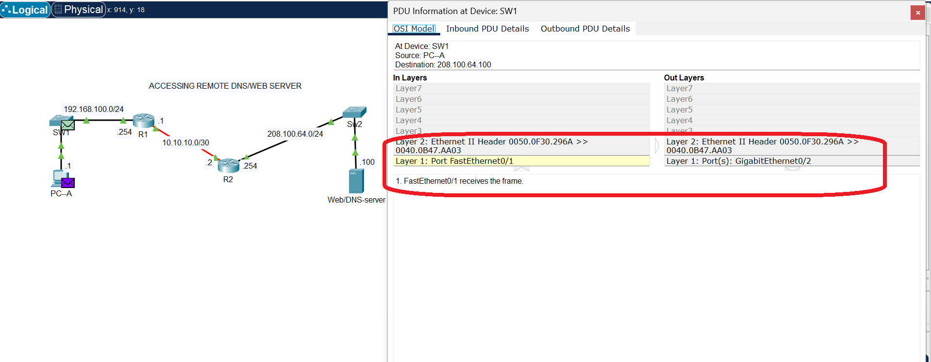
The Ethernet header contains source and destination MAC addresses. A MAC (Media Access Control) address is a physical, hardware-burned address that is unique to a network interface card (NIC). The Ethernet header is what a switch uses to move the data between devices on the same local network. The switch uses the destination MAC address to send the packet to the correct device on the network segment. The source and destination MAC addresses change at every “hop” (e.g., from your computer to the router, and then from the router to the next router), while the IP addresses remain constant throughout the journey.
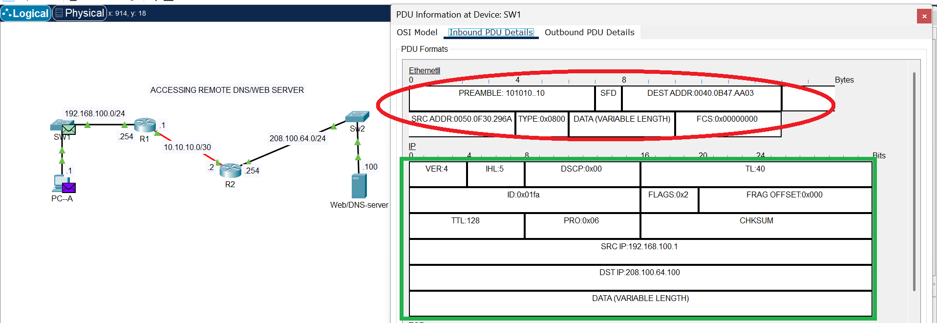
Ethernet Header
In the image above, the Ethernet header is circled in red ink. This shows the Ethernet header at the source local network, when the frames entered the connected port on SW1.
Ethernet’s role is to handle the specifics of data transfer at the second layer of the OSI model, focusing on local communication rather than routing across the internet. Its main functions include:
- Framing: Ethernet takes data from the network layer (e.g., an IP packet) and wraps it in an Ethernet frame(Encapsulation). This frame includes a header and a trailer, which contain essential information for delivery.
- Addressing: The Ethernet header contains the MAC (Media Access Control) address of both the source and the destination devices. The MAC address is a unique, physical address assigned to every network interface card (NIC), ensuring that each frame is delivered to the correct device on the local network.
- Access Control: Ethernet uses a protocol called CSMA/CD (Carrier Sense Multiple Access with Collision Detection) to manage access to the shared network medium. Before sending a frame, a device “listens” to the network to see if it’s clear. If a collision (when two devices transmit at the same time) is detected, both devices stop, wait a random amount of time, and then try again. This prevents data from being corrupted. (Note: CSMA/CD is mainly used in older half-duplex Ethernet (e.g. Hub); full-duplex Ethernet, which is more common today, does not use this protocol.)
- Error Detection: The Ethernet frame includes a Frame Check Sequence (FCS) in its trailer. This value is a result of a mathematical calculation on the data. The receiving device performs the same calculation; if its result matches the FCS, the frame is considered intact. If not, the frame is discarded, preventing corrupted data from being processed.
Layer 1: The Physical Layer
The physical layer is the lowest layer of the OSI model, responsible for the physical transmission of raw data bits over a communication medium (electrical impulse, light impulse or electromagnetic wave). At this stage (Physical Layer), the entire frame (which includes the data, and the TCP, IP, and Ethernet headers) is converted into a series of electrical signals, light pulses (on a Fibre optics network), or radio waves (Wireless network). This is the actual physical transmission of the data over the network medium (e.g., Ethernet cables, fiber optics, or Wi-Fi signals).
Ethernet Port
Transmission over copper cable
The processes at this layer are highly hardware-dependent and ensure the bits get from one device to another. They include:
- Bit-by-Bit Transmission: This layer takes the data frames from the data link layer and converts them into a stream of individual bits to be sent over the physical medium. It doesn’t care about the meaning or content of the bits—it just sends them one after another.
- Signaling and Encoding: This is where the digital bits are converted into physical signals. For a wired network, this might involve converting a 1 or 0 into a specific electrical voltage level. For a wireless network, it’s about converting the bits into radio waves. This process also includes encoding, which defines how bits are represented by the signal to ensure the receiving device can correctly interpret them.
- Synchronization: The physical layer ensures that both the sender and the receiver are synchronized. This is crucial for bit synchronization, where the receiver knows exactly when a new bit starts and ends, preventing misinterpretation of the data stream.
- Medium and Topology Definition: The physical layer is responsible for defining the physical medium (e.g., copper cable, fiber optic cable, or wireless radio waves) and the physical network topology (e.g., star, bus, or ring). It also specifies the hardware components like connectors, cables, and network interface cards (NICs).
- Transmission Mode: This layer determines how data flows. It can be a simplex (one-way, like a radio broadcast), half-duplex (two-way but not at the same time, like a walkie-talkie), or full-duplex (simultaneous two-way communication, like a telephone call).
Life of a packet (Summary)
The life of a packet is a continuous cycle of encapsulation and decapsulation:
- Source Host: The application data is segmented and a TCP/UDP header is added.
- Encapsulation: The segment is wrapped in an IP header, creating a packet.
- Encapsulation: The packet is then wrapped in an Ethernet header, creating a frame.
- Physical Transmission: The frame is converted into electrical signals and sent out on the network.
- Hop to Hop: When the frame reaches a router, the router removes the Ethernet header, inspects the IP header to determine the next hop, adds a new Ethernet header with the new destination MAC address, and sends it on its way.
- Destination Host: The packet goes through this process of decapsulation at each layer. The Ethernet header is removed by the switch, the IP header is removed by the router, and finally, the TCP/UDP header is removed by the destination host’s operating system.
- Reassembly: The data is reassembled at the application layer and delivered to the correct application, completing the packet’s journey.